The following Post is not intended to be a set of plans
showing how-to-build-yourself a copy of what I built. Instead, this is a description of “how” I
built a homemade pinball machine for my grandkids.
I have intentionally omitted exact measurements, because,
should you decide to build one, that will all vary based on what materials you
may have on hand or can scrounge. Most
of the information you need to build your own can be gleaned from the photos and
descriptions.
On occasion, my wife and I get to spend some quality “Grammy
and Grampa” time with our out-of-state grandkids. When we go we always try to take along some
“hands-on” activities. Sometimes we hit
the ball out of the park with our choices…other times…well, not so much. It is difficult to always match the varied
interests and abilities of 4 young children who are rapidly growing, developing
and evolving.
I’m not exactly sure how this particular idea came to mind
but my wife found this YouTube video of how someone else built his own Pinball Machine. It seemed like it might be a good choice for
a project for the kids. The plan was to design
and build a Pinball machine in my workshop, then disassemble it and then
reassemble it at their house with the aid of 8 and 9 year old hands. The thing does make noise and “could” provoke
arguments so I needed to clear it first with their parents. After receiving a green light from them, I
began work.
I admit that I copied many of the features that I saw in the
video but like practically everything else I do, I decided to modify the design
to suit my tastes and my unusually large and varied junk box. I decided to use small (1” dia.) rubber balls
rather than the marbles the video showed. Someone else suggested the rubber –coated
roller balls out of computer mice, and I have to admit, they would be an
excellent choice, but, my junk box was sadly lacking there.
Photo Number 1 is an overall view of my completed, ready to
play, but as yet unpainted, pinball machine.
My unit happens to be about 24” x 36”. The size was “strongly influenced” by the
chunk of ¾” nice birch plywood that I happened to have. I needed to get all four sides, the legs and
the flippers out of that one piece and I just about used it all up. The Pinball machine in the video was built
around a piece of Melamine tabletop. I
didn’t have any of that but I did have a nice, new piece of “Peg-board” and
decided to use that instead.
Using the table saw, I cut the four sides to width and
length. I then cut a 3/16”wide groove (to
fit the Peg-board) near the bottom of all four pieces. I then inserted the peg-board and drilled and
screwed the four sides.
It would have been “nice” to have nicely mitered corners to
hide the grooves. Unfortunately, my
table saw isn’t very good and does not handle cutting miters very accurately,
so I just used butt joints. Admittedly,
the slots are visible on the ends of the two side pieces, but I don’t
think it would have been worth the additional effort to hide them.
 I added two short legs at the back to put the playing field
at about a 7°or 8° angle. The exact angle isn’t too critical but make
sure to make both legs exactly the same length and with the same angle. I used three screws to ensure that the legs
couldn’t wiggle loose with the excitement of play. Not shown in this photo were two adjustable “feet”
added to the bottoms of the legs. I
drilled and inserted them in the ends to allow for a means of leveling the
table. In retrospect, that was probably
not a great idea. The pinball machines size
dictates that it must be played on a table and if the table is slippery (like
the one at their house) it slides around way too much. If I had it to do over, I would skip the
adjustable feet and glue a piece of anti-slip/anti-scratch material on the
bottom of each foot. That would protect
the table but still “grip it” and minimize the sliding.
I added two short legs at the back to put the playing field
at about a 7°or 8° angle. The exact angle isn’t too critical but make
sure to make both legs exactly the same length and with the same angle. I used three screws to ensure that the legs
couldn’t wiggle loose with the excitement of play. Not shown in this photo were two adjustable “feet”
added to the bottoms of the legs. I
drilled and inserted them in the ends to allow for a means of leveling the
table. In retrospect, that was probably
not a great idea. The pinball machines size
dictates that it must be played on a table and if the table is slippery (like
the one at their house) it slides around way too much. If I had it to do over, I would skip the
adjustable feet and glue a piece of anti-slip/anti-scratch material on the
bottom of each foot. That would protect
the table but still “grip it” and minimize the sliding.
 Of course, the heart of any pinball machine is, for lack of
a better name, “the shooter.” The over
all length of the “shooter channel” is about 18”. I made mine out of some pine strips that I ripped
from of a chunk of 2x4.
Of course, the heart of any pinball machine is, for lack of
a better name, “the shooter.” The over
all length of the “shooter channel” is about 18”. I made mine out of some pine strips that I ripped
from of a chunk of 2x4.
Do yourself a favor.
Carefully cut and drill the cross pieces in the shooter so that they are
square and exactly the same. The
same is true of the side pieces. Otherwise,
you are likely to experience binding of the rod sliding through the holes (this
is personal experience talking, here).
The first version used a ¼” wooden dowel rod as the shaft of
the shooter. However, when I was trying
things out during my initial trial fitting, I noticed that the metal locking collar
(used to push against the spring as the shooter is pulled back, see sketch
below) tended to slip on the dowel rod because it always smacked the middle
support whenever it was released.
Tightening the screw in the collar to prevent slippage only further
damaged the dowel rod. It was only a
matter of time before something would break and by that time Grammy and Grampa
would be several hours away making retrofits difficult to accomplish.
So, I rooted around a little farther down in the junk box
and found a length of ¼” mild steel rod.
I cut it to length and drilled two small dimples in the rod to accept
the screws from the collar and the pull-knob so they couldn’t slip with
use. You could use a wooden dowel
for the center rod, but I would go to at least 5/16”in diameter and would
use some sort of locking screw or pin through the shaft to ensure that the knob
and collar cannot slip. I used odd
pieces of ¾” and 1-1/4” dowel rod for the tip and knob of the shooter. The dowel on the tip does not require the
little dimple in the rod because in operation it is always being pushed “on
to”, not “off of” the rod.
I screwed the shooter channel into the lower right hand
corner of the frame from the bottom only.
CAREFULLY, measure to locate the hole for the shooter rod to come
through. You might want to make that
hole a size or two larger through the frame to prevent any binding. You really want that ball to fly out
of there.
(Later note: I re-drilled the hole for the screw in the
wooden knob clear through so that the screw would have a really solid hold on
the steel rod and the knob couldn’t be pulled off.)
Bear in mind as you are building the “shooter channel” that
the right-hand-flipper control rod also has to pass through it (either over or
under the steel rod) to hit the right-hand-flipper. In this photo, you can see
that mine passes over the rod. It
doesn’t really matter which path you use, but you want both flippers to be the same and
you need to decide which path you want to
use before you get too far into the project and certainly before you go
drilling holes in the frame where they will really show.
With the channel firmly in place, drill the 3 holes (the
frame and both sides of the channel) at the same time. Here again, you “might” want to drill out the
hole in the frame a size to two larger to prevent binding. A little paste wax on the flipper dowel rod
is a good idea, too.
I played around quite a bit with the design of the flippers. What you see represents what was, I think, my
third variation. They consist of two
pieces of ¾” plywood glued together and cut into an “L” shape. I drilled a ¼” diameter hole in the corner of
each “L” to act as the pivot point. I also
played around with where to locate the flippers. That was one of the advantages of using the
pegboard. There are ¼” holes every 1” in
both directions, so you can play around to decide on the best locations for the
various bits and pieces without damaging anything.
I made the pivot out of a 2-1/2”- ¼-20 machine bolt. Since I expect that the flippers are going to
get a real work out, I used two fender washers (1 on top and 1 underneath) and
tightened the locking nut to prevent any “wiggling” or damage to the Masonite
Peg board.
When installing the flippers, I used a flat washer on both and
bottom of the flipper and their respective nuts. I placed a second “jam” nut on top of the
first. Make sure that your flipper moves
freely. If not, loosen both nuts, hold
the lower nut in place with an open-end wrench and retighten the jam nut.

 In order to give the left flipper control rod the same sort
of “bearing” surface as the right side (to prevent it from “wiggling” when smacked)
I added a small additional block and drilled through the frame and the block at
the same time. I cut and drilled two
small lengths of ¾” dowel to act as the contact blocks on the ends of the
flipper control rods. The discs glued onto the outside ends of the control rods
are wooden toy wheels from…you guessed it…the junk box!
These two photos show the left flipper in both the “open”
and “rest” positions. I hooked some
heavy, “matched” rubber bands to big screw-eyes to retract the flippers and pull
the control rod back into rest position.
In order to give the left flipper control rod the same sort
of “bearing” surface as the right side (to prevent it from “wiggling” when smacked)
I added a small additional block and drilled through the frame and the block at
the same time. I cut and drilled two
small lengths of ¾” dowel to act as the contact blocks on the ends of the
flipper control rods. The discs glued onto the outside ends of the control rods
are wooden toy wheels from…you guessed it…the junk box!
These two photos show the left flipper in both the “open”
and “rest” positions. I hooked some
heavy, “matched” rubber bands to big screw-eyes to retract the flippers and pull
the control rod back into rest position.
 You will notice that I added two straight blocks to stop and
hold the flippers in their “relaxed” locations.
You will notice that I added two straight blocks to stop and
hold the flippers in their “relaxed” locations.
I flexed and wedged a length of a wooden Venetian blind slat
(~1/8” thick) between the top of the shooter channel and a small block in the
middle of the back frame piece. One inch
wide Basswood slats (from the junk box, again) are flexible enough to form a
nice arc to keep the ball from getting stuck in the upper right-hand
corner. Bear in mind that the Basswood will
snap if you get too vigorous with the bending.
I fashioned a little triangular block with a little hook to hold the
slat in place from the back side.
You can just make it out near the center of the arc in this photo.
For interest, I added 6 bumpers, made from 1-1/4” dowel
about 1” long. I drilled and inserted a
piece of ¼” dowel to locate the bumpers at the desired locations on the
peg-board. I also cut two “C” shaped goals. I spent quite a bit of time playing with the
semi-finished game trying to find the best location for the bumpers. Although I started out with a very
non-symmetrical arrangement, I finally decided that the very regular “upside
down face” arrangement worked pretty well.
The bumpers are glued down. The
goals have dowel rods to locate them but are screwed down from the bottom side.
I also added a few random angled pieces to deflect the ball from corners and the ends of the flippers.
Did the project work?
Did the kids enjoy their role as “assemblers”? Judge for your self from the following video taken just minutes after the project was completed:
'Til Next time...Keep Makin' chips

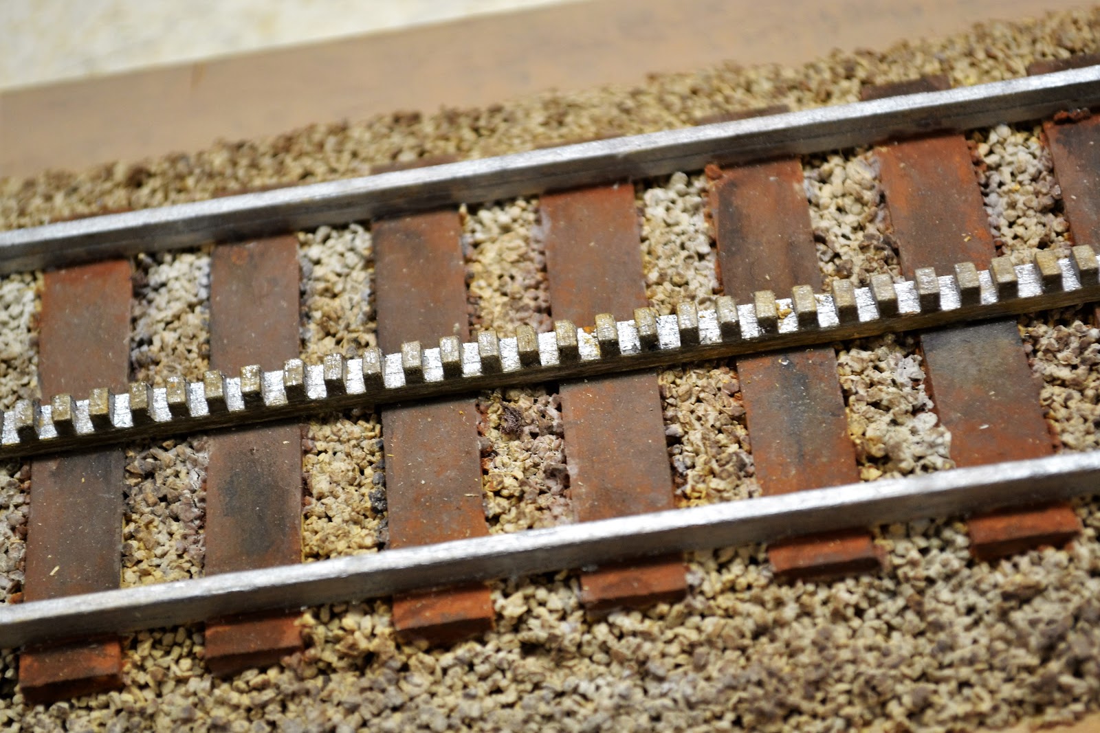
 I
did not even attempt that level of accuracy. As it was I laboriously cut and glued many
(!) tiny teeth to a strip of basswood.
To do two rows of even smaller teeth was just out of the question.
I
did not even attempt that level of accuracy. As it was I laboriously cut and glued many
(!) tiny teeth to a strip of basswood.
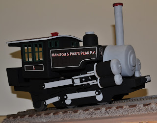
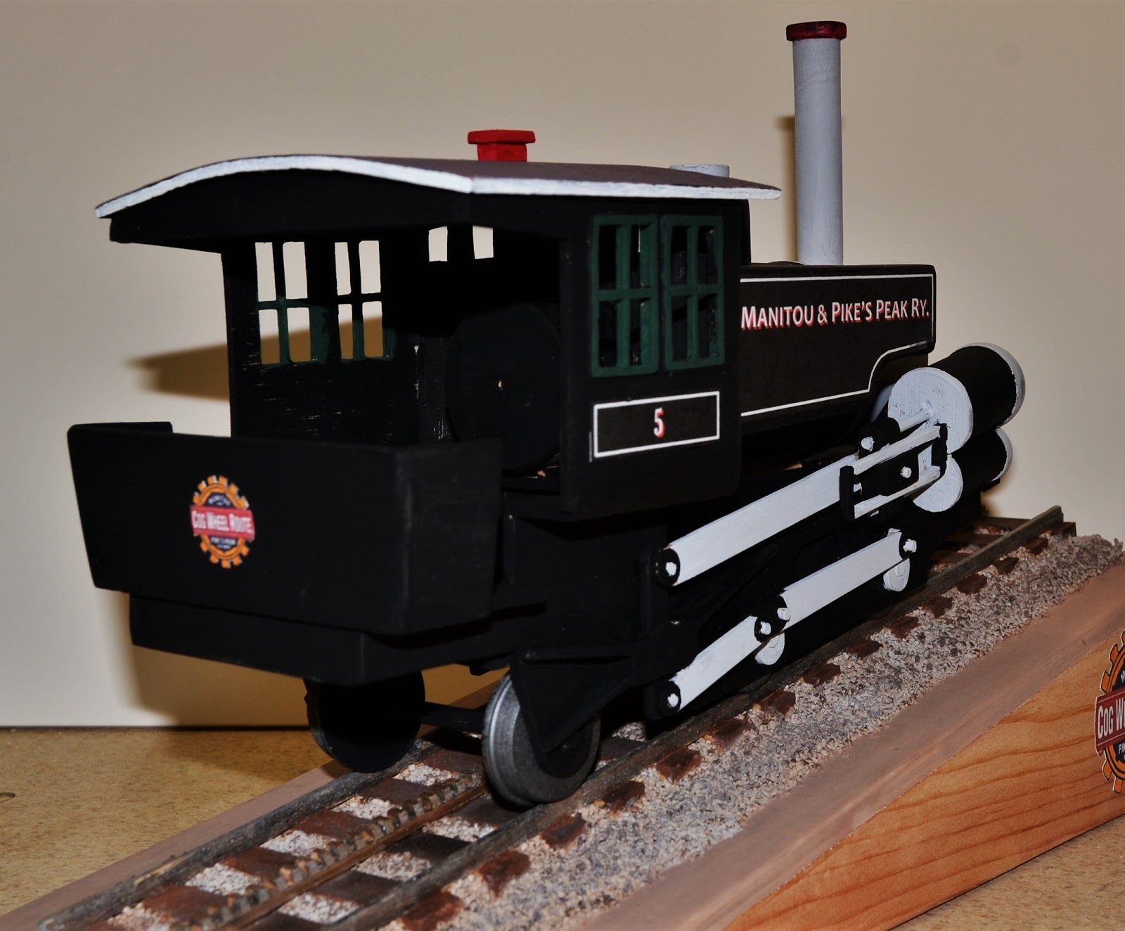
To do two rows of even smaller teeth was just out of the question.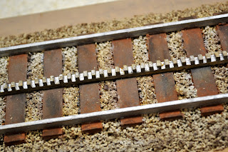 Another feature about the locomotive is that
the boiler tank is mounted at an angle to the wheels so that it remains
relatively level for maximum efficiency and, probably, safety as it the
locomotive hits the steeper sections of the track. If you saw the locomotive sitting on level
track (like this one), you might wonder if a giant hadn’t come along, picked it up, dropped and
broken it.
Another feature about the locomotive is that
the boiler tank is mounted at an angle to the wheels so that it remains
relatively level for maximum efficiency and, probably, safety as it the
locomotive hits the steeper sections of the track. If you saw the locomotive sitting on level
track (like this one), you might wonder if a giant hadn’t come along, picked it up, dropped and
broken it.