Friday, September 20, 2013

The Carving of a Full size Replica of an 1861 Remington Cap and Ball Revolver – Part 3


Painting
 
I wasn't all that pleased with the color and texture of the metal parts of the 1884 Springfield Trapdoor Rifle that I had carved about 5 years ago (see below). I vowed that this time my results would be much better. 

Close up of Trapdoor Rifle Replica.
Note the flat “cast iron” look of the Lock and Hammer
The acrylic paint that I used on the rifle looked "OK".  It has fooled a lot of people, particularly if they are more than 4 feet away.  It looked "old", which is what I was going for but it just didn't look all that "metallic" to me.  The finish was flat and looked like it had been "piled on", which was exactly what it was, the result of many, many washes of all sorts of colors.

I took the unpainted revolver with me to discuss the paint selection with the guy at my favorite hobby store to see what he would suggest.  He recommended a 2-step, Spray-on lacquer from Testor's to make it look more like metal.  The first coat was Number 1454 "Titanium" Model Master Buffing Metalizer.  Since this was going to be an "all-or-nothing" kind of procedure, it required a lot of thought, quiet meditation and mental preparation before I was ready to commit to the paint application.  I really didn't want to ruin my work so far.  Finally, I realized that if this methodology didn't work out, I was no worse off than I was the last time.  So I took the plunge!

At first, I was more than just a bit disappointed when I saw the results...the finish looked way too flat...not much of an improvement over the acrylic.

However, the hobby store guy made a big point of telling me that this paint requires "buffing" to bring out the shine.  Sure enough, once it was dry -- which only took about 10 minutes -- a few seconds of buffing with a Facial Tissue and it began to shine.  The frame and barrel looked "old and shiny" just the way I hoped it would.  The second step is essentially a "clear coat" (Testor's 1459) to seal and protect it.

This photo was taken before I got around to applying the antique brass color to the trigger guard and finalizing the color and finish on the handles, but after what happened so far those things should be a piece of cake...or so I thought!


Preliminary Photo of 1861 Remington Revolver
(the trigger guard and handles were not complete)

I already posted this next part but I think it is important enough to repeat.

The antique brass paint went on without a hitch.  When I dried I decided to give the “now complete” revolver a good, protective coat of paste wax as I do with nearly all of my carvings.  Unfortunately, that is where I discovered:

Cautionary Note #1 - When using the lacquer based finishes, DO NOT use a paste wax to seal the carving.  The solvents therein will attack the lacquer.

The antique brass colored paint that I had applied to the trigger guard was extremely sensitive and much of it just came off in the application rag.  After a suitable amount of recovery time had expired -- not for the finish, but for my psyche -- I carefully re-sanded the trigger guard to ensure that the wax was completely gone and then reapplied the antique brass paint.  “Job done”, right? Yes, you’d think so, but then you would be wrong.

You have probably heard of the corollary to Murphy's Law called "the Law of Selective Gravitation" which states that "A dropped tool will always land where it can do the most damage".  Well, I encountered yet another corollary to that corollary.

After completing the painting of the trigger guard I placed the revolver on the Mantle to "keep it out of harm's way".  But instead of laying it flat where there was the risk of "perhaps" scraping it against the rough brick surface along the back wall, I propped it up so that the trigger guard wouldn’t touch anything.  About 2 hours later, I encountered a third corollary.

Cautionary Note #2 - When storing a finished, but oddly shaped carving on the Mantle, do not prop it up but instead lay it flat.

I heard a loud noise and checked to see what had happened.  Whether it was due to some localized seismic event or just a passing of some unhappy apparition, the revolver was on floor sporting a very nasty crack right below the barrel.  I was sick!
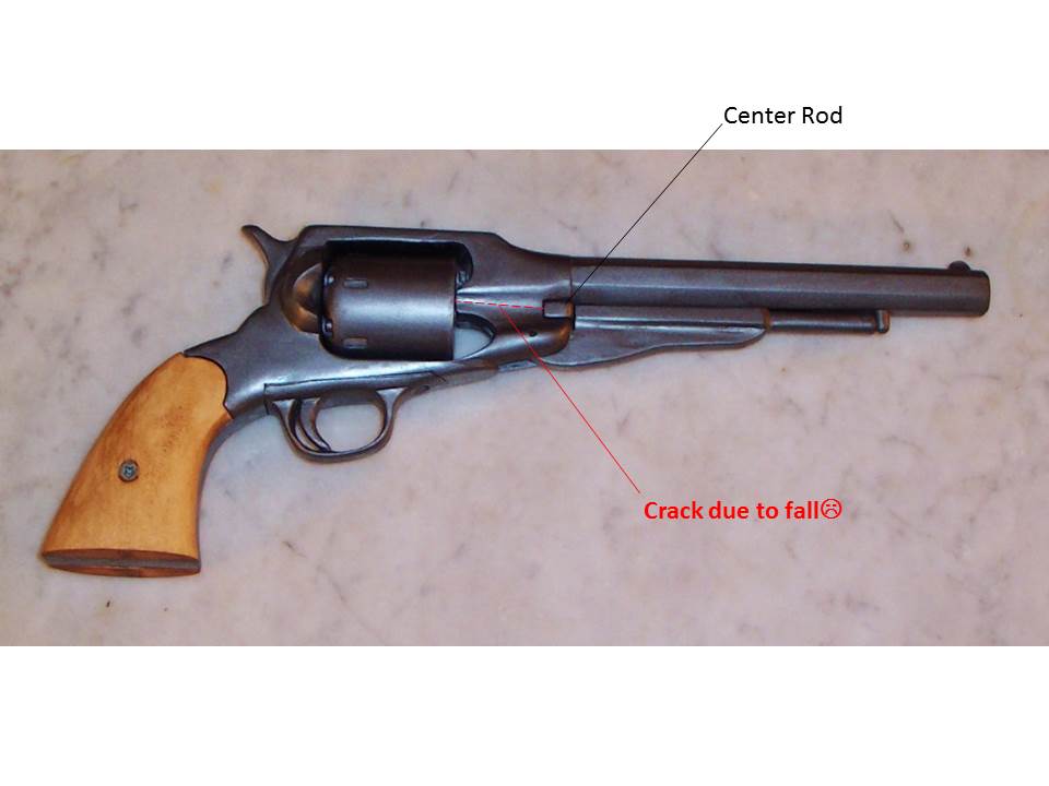
Location of Crack due to Fall from Mantle

Fortunately, using a little Elmer's Glue and a nice big rubber band I was able to mend the flaw.  As you might expect, the crack occurred at the weakest point: under the barrel, at the thinnest part of the frame and right where the cylinder center rod goes through.  The glue managed to savage the entire project.  There is a small, barely visible scar left where I added the glue.  I did have to sand the -- now misshapen -- center rod hole a bit to get the rod back in place.

What this did is confirm that in order to ensure that the carving remains in one piece, I will definitely have to go ahead with my idea of placing the revolver in a "presentation" box.  Manual fondling of the revolver is -- Apparently -- no longer a reasonable consideration.

Final Pictures

Left Side View


Left Side View with Loading Lever Down


Right Side

It was quite a long haul.  There were a lot of little pieces with a lot of places to make mistakes (I made 'em) but I am quite pleased with the results.  Now to get the other pieces finished and get them into the presentation box.

I hope you found this interesting.

'Til Next Time...Keep Makin' Chips!


The Carving of a Full size Replica of an 1861 Remington Cap and Ball Revolver – Part 2


Making the Cylinder
 
Unless you have access to a lathe, making the Cylinder is liable to be the most difficult portion of the project.  It is “carve-able” but getting it round will require some real effort.

Once the cylinder was turned, I took a strip of paper that was as long as the circumference of the cylinder and subdivided it into 6 equal parts.  I wrapped the paper around the cylinder and marked the locations of the 6 chambers on 60˚ spacing. 

I drilled out the chambers, flipped it over and drilled the percussion cap “pockets”.    I drilled a 3/16” diameter into the center of each of pockets and glued a short piece of 3/16 dowel into each hole.  This results in a reasonably good looking percussion cap “nipple”.

A couple words of advice on how to hold the cylinder steady so that you can drill the holes.  

·         Unless you have a very steady hand, I would not try this without a drill press.
·         I recommend using a brad-point drill bit.
·         Drill a ¼” hole in a piece of scrap lumber and insert a short length of dowel rod.
 
This will ensure that the cylinder will remain vertical while you drill.
·         I wrapped a small rubber strap wrench around the body of the cyilnder
       to prevent the cylinder from moving while I drilled.

Making the Barrel

I recently read a tip that I used in the laying out of the barrel.  While the grain runs generally in the direction of the barrel’s length, I didn’t cutout exactly along grain line.  The reason for this is that it is very difficult to carve a straight line directly along the grain because the grain is constantly trying to align your cut with the grain.  This can result in a very crooked line.  By intentionally skewing the centerline slightly away from the grain line you retain most of the strength without being a slave to the grain direction.

I turned the “threaded” portion of the barrel (i.e. the part that “screws into the frame”) between centers taking great care to make that portion straight, smooth and true.  I turned a few grooves in the last 3/8” or so this portion to simulate the threads on the barrel.  Make them as small and close together as you can.

I next chucked up the barrel in a vise and drilled the “bore hole” of the barrel.  You don’t want to drill very deep because that will just weaken the barrel.   I went about 1” deep so that when it is painted black it “appears” to go the whole way through.  

I shaped the four major sides of the barrel first, and then attacked each of the corners until all 8 sides were uniform.  Note there is a slight taper to the barrel.  I used a small wood plane to shape the barrel partly because I could and I knew it would be the quickest, truest way to shape it but mostly because there is something truly magical about using a plane. That “shhhhhhwock” sound it makes as you draw it along and that paper thin curl of wood that shoots out makes planning a truly satisfying experience.  If you’ve never done it before try it!  

Making the Trigger and guard

Although it could have been left as part of the overall frame, I intentionally left the trigger guard a separate piece.  The reason I chose to do this is sort of historical.  When I carved the rifle, I found that I could make it look much more realistic by carving each “assembly” and letting it into the stock as a gunsmith would have done.    

Cut the piece out and drill through between the trigger and the guard.  It is attached both at the top and bottom to inhibit its being snapped off due to rough handling.  

The only other advisory is to ensure that the upper surface of the trigger guard and the lower surface of the frame are both flat so that they glue together well.  I didn’t worry too much about hiding the seam because the trigger guard will be painted antique brass and retaining the seam will make that easier to accomplish.

Carving the Hammer

There is not much to say about this.  I cut out the entire hammer from a piece of ~1/4” thick basswood.  However, with the grain running up and down there is not much strength in the hammer and it could possibly break off with even normal handling.  So before running to the bandsaw, I drilled a 1/8" hole into the hammer from the rearmost tip of the of the hammer and glued a 1/8" dowel rod.  Once the glue had dried, I cut out the piece and carved and sanded it to final shape.

Carving and Installing the Loading Lever

Since this was a cap and ball revolver and because the cylinder lies within the frame of the revolver during loading, it was necessary for Remington (Colt did it, too) to make provision for an internal “ramrod” to compress the ball into place over the black powder.  The ramrod is operated by the loading lever located beneath the barrel.  Rotating the loading lever down and to the rear forces the ramrod it against the ball of the cylinder chamber oriented behind it.  

This is one place where the replica had to make serious deviation from reality.  The just wasn’t room within the revolver’s frame to allow for the loading lever, the ramrod and the tiny linkage to connect them. So, the linkage and the ramrod were omitted – you really wouldn’t be able to see them very well anyway.  I couldn't make a "real" catch to hold the loading lever up but I did provide for the loading lever to move and then be locked back in place under the barrel.  I located some very tiny neodymium magnets (.050 in diameter and .050 long) on the Internet and inset one into the underside of the barrel and another into the top surface of the loading lever.  When returned to the “fully upright and locked position”, the lever literally snaps into position.  If you chose to use this technique, make sure that you maintain the proper North-South orientations for the two magnets or your loading lever will never lock in place but will fly open every time you attempt to close it:-).


End of Part 2

The Carving of a Full size Replica of an 1861 Remington Cap and Ball Revolver – Part 1


I am embarrassed to admit that it was some 2 years ago (!) when I promised myself and all of my loyal readers that I would embark on a new project: the rendering of a 1861 Remington revolver in wood (what else?) with construction details so that anyone else who was interested could do the same thing.   I’m not sure exactly what intervened but I am finally achieving that goal.   Here is the goal!  Good looking isn’t it!  No, this is a real one, but you’ll see my finished gun soon enough.
 
The Real Thing!

What I was looking for and how I found it

I wanted to recreate something that was old to go along with the 45-70 Springfield “trapdoor” rifle, circa 1884, that I had carved back in 2009.  Originally, I thought that I would do the 1851 Navy Colt Revolver based on its historical cache but I soon decided that the lines of the Remington were more pleasing and, after all, this is “art”.  While the Colt came first and introduced the whole idea of placing the rounds into a rotating cylinder that, once fired, would shift the next round into position when the weapon was re-cocked, it just didn’t have the “look” that I was after.

As I always do, I spent a great deal of time rooting around on the Internet looking for views of the gun from all angles.  Actually, this process also helped some in the selection of the gun to be carved.  When I viewed the Colt and the Remington side by side, I could see why the Remington also did well in the market.  It was very handsome and the upper strap (the portion of the frame that lies above the cylinder) added to its ruggedness and provided the users with the option additional “punch” because it had the strength to be “packed heavy”, unlike the Colt.  Through a bit of Internet snooping I discovered that all cap and ball revolvers required daily dis-assembly and cleaning to prevent fouling.  One of the reasons why big name gunslingers e.g. Wyatt Earp and Wild Bill Hickok chose the Colt over the Remington was that it was easier and quicker to clean.  And, in their line of work, the less time they spent “out of operation” the better.  OK, that’s a valid argument but I still think that the Remington is “prettier”. :-)   The 1861 is often referred to as the 1858. Actually, as I understand it, they are actually the same piece.  The 1858 date I often used because that is when some of the patents involved were dated.

Now, if you jes’ happ’ned to be packin’ this here piece as you strolled on down Main Street towards the Longbranch Saloon, you’d very aware you had it with you.  This thing was enormous!  It measured 13.25 inches long from the tip of the handle to the tip of the barrel and it weighed in almost 3 pounds (!) (Actually, 2 lbs., 13 oz.).  The overall barrel length was a respectable 8”.  It is no wonder that a cowboy’s spurs jingled with this monster was strapped to his leg:-). 

It is my understanding that after impressing everyone in Dodge City, most hand guns were generally relegated to a place on your saddle when you left town.  As long as it was handy for use, it didn’t need to be pounding on your leg the whole time that you traveled.  No matter how cool it made you look. 

While I obviously never harbored any illusions of making this weapon capable of actually being fired, I did want to make things as realistic looking as possible.  The loading lever moves, the cylinder rotates and the center rod can be removed to free the cylinder.

What I found in the way of Research Materials

Much to my delight, due to its popularity with collectors, there is a wealth of photos if you just Google “1861 Remington Cap and Ball Revolver.  The biggest help that I found was a really fine line drawing of the gun (see below).  Given that drawing, I could scale almost dimension off of any photo.  Make yourself a couple of full size prints of the line drawing.  You’ll be referring to them a lot during the process.
 
Someone sent me this exploded view.  I filled in some of the names (as I know them) that we will be talking about later.
Exploded view
Cutting out the Frame

I cut the frame out of ¾” basswood.  The job is pretty straight-forward so I won’t belabor it here.  Just go slowly.  There is not a lot of “meat” associated with the top strap, so be careful while shaping it.

Unlike the real revolver where weight was a consideration, I did not cut out the area inside the handle.  Once I had determined the position for the screws that would be used to hold the handles on, I drilled out the hole in the frame to ¼” diameter.  I pressed in a 6-32 x 7/16” or 6-32 x 1/2" hexagonal threaded standoff widely used in the electronics industry (see http://www.keyelco.com/userAssets/file/M60-2p71.pdf).  In case you have never seen these things, they are like an elongated machine nut with threads running the whole way through.  It is an easy press-fit into the soft basswood and as long as I remember to tighten the two screws carefully and equally I don’t need glue because the two screws pull against one another.  Its hexagonal profile keeps it from rotating in the undersize round hole. 

This brings us to what I call the “cheek pieces”.  I’m sure that there is some “real” name for them but I sure don’t know what it is.  They form the portion of the frame that curves around the rear of the rotating cylinder to help prevent anything from dislodging the percussion caps from their position at the end of each of the chambers.  Because the ¾” thickness of the frame is not quite thick enough to include I glued two small chunks of basswood to the frame and carved them to shape.  The right-hand cheek of most modern revolvers includes a “loading gate” to give access for inserting cartridges.  The 1861 has a rounded notch to give the loader just enough finger room to snap the caps in place.  Despite this design feature, I’ll bet that many “misfires” were due to the inadvertent loss of a percussion cap.

Drilling the Frame for the Barrel and Center Rod

I drilled two holes in the front of the frame.  This job requires a good drill press vise to keep them in position and square to the frame.  

The upper hole accepts the threaded portion of the gun barrel.  The actual diameter of the thread is about 5/8”to allow for a 0.44” bore, but since this is not intended to be a “firing” weapon I brought that portion down to ½” so that I could use a common Forstner bit to drill out the frame and leave more wood in place after drilling the frame.  If you look at figure 1, you can just catch a glimpse of the threads right in front of the cylinder.  I figured that a little extra “meat” left on the frame would be good and that it is pretty well hidden.

The second hole is for the center rod that serves as both the containment and the pivot for the cylinder.  Drilling this one is more difficult that you might expect.  You will need a much-longer-than-usual 1/4” drill bit and even then you might end up grasping it be the very end to reach all the way into the back side of the frame.  Here’s a drilling guide to help you located the holes in the frame.

Frame Hole Drilling Info

End of Part 1